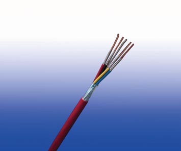
300/500V XLPE Insulated, LSZH Sheathed, Screened Power Cables (2-4 Cores)
FTX200 05ROZ1-R (CU/XLPE/OSCR/LSZH 300/500V Class 2)
APPLICATION
The cables are mainly used in power stations, mass transit underground passenger systems, airports, petrochemical plants, hotels, hospitals, and high-rise buildings.
STANDARDS
- Basic design adapted to BS5308 Part 1 Type 1
FIRE PERFORMANCE
| Flame Retardance (Single Vertical Wire Test) |
EN 60332-1-2; IEC 60332-1-2; BS EN 60332-1-2; VDE 0482-332-1; NBN C 30-004 (cat. F1); NF C32-070-2.1(C2); CEI 20-35/1-2; EN 50265-2-1*; DIN VDE 0482-265-2-1* |
| Reduced Fire Propagation (Vertically-mounted bundled wires & cable test) |
EN 60332-3-24 (cat. C); IEC 60332-3-24; BS EN 60332-3-24; VDE 0482-332-3; NBN C 30-004 (cat. F2); NF C32-070-2.2(C1); CEI 20-22/3-4; EN 50266-2-4*; DIN VDE 0482-266-2-4 |
| Halogen Free |
IEC 60754-1; EN 50267-2-1; DIN VDE 0482-267-2-1; CEI 20-37/2-1; BS 6425-1* |
| No Corrosive Gas Emission |
IEC 60754-2; EN 50267-2-2; DIN VDE 0482-267-2-2; CEI 20-37/2-2 ; BS 6425-2* |
| Minimum Smoke Emission |
IEC 61034-1&2; EN 61034 -1&2; DIN VDE 0482-1034-1&2; CEI 20-37/3-1&2; EN 50268-1&2*; BS 7622-1&2* |
| No Toxic gases |
NES 02-713; NF C 20-454 |
Note: Asterisk * denotes superseded standard.
VOLTAGE RATING
300/500 V
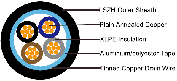
CABLE CONSTRUCTION
| Conductor |
Plain annealed copper wire, stranded according to IEC 60228 class 2 |
| Insulation |
Extruded XLPE compound |
| Filler, binder(if any) |
PP, Mylar tape |
| Circuit Protective Conductor |
Annealed plain copper (class 2) |
| Overall Screen |
Aluminium/polyester tape |
| Outer Sheath |
Thermoplastic LSZH compound type LTS3 as per BS 7655-6.1. UV resistance, hydrocarbon resistance, oil resistance, anti rodent and anti termite properties can be offered as option |
COLOUR CODE
Insulation Colour as per BS7671
| |
With Earth Conductor |
Without Earth Conductor |
| 2 Cores |
- |
Brown, Blue |
| 3 Cores |
Yellow/Green, Brown, Blue |
Brown, Grey, Black |
| 4 Cores |
Yellow/Green, Brown, Grey, Black |
Brown, Grey, Black, Blue |
| 5 Cores |
Yellow/Green, Brown, Grey, Black, Blue |
Brown, Grey, Black, Blue, Black |
| Above 5 Cores |
Yellow/Green, Black Numbered |
Black Numbered |
Sheath Colour: Black (other colors upon request)
PHYSICAL AND THERMAL PROPERTIES
| Maximum temperature range during operation (XLPE) |
90°C |
| Maximum short circuit temperature (5 Seconds) |
250°C |
| Minimum bending radius |
6 x Overall Diameter |
CONSTRUCTION PARAMETERS
| Conductor |
FTX200 05ROZ1-R |
| No. Of Core X Cross Section |
No./Nominal Diameter Of Strands |
Nominal Overall Diameter Conductor |
Nominal Insulation Thickness |
Cross-Section Area
Of Circuit
Protective Conductor |
Nominal
Sheath Thickness |
Nominal
Overall Diameter |
Max.Dc Resistance
Of Conductor @20°C |
Approx.
Weight |
| Noxmm2 |
No./mm |
mm |
mm |
mm2 |
mm |
mm |
Ω/km |
kg/km |
| 2x1.0 |
7/0.44 |
1.32 |
0.6 |
1.0 |
0.9 |
8.1 |
18.1 |
79 |
| 2x1.5 |
7/0.53 |
1.59 |
0.7 |
1.5 |
0.9 |
9.1 |
12.1 |
102 |
| 2x2.5 |
7/0.67 |
2.01 |
0.8 |
2.5 |
1.0 |
10.5 |
7.41 |
146 |
| 2x4.0 |
7I0.85 |
2.55 |
0.8 |
4.0 |
1.1 |
11.8 |
4.61 |
205 |
| 3x1.0 |
7I0.44 |
1.32 |
0.6 |
1.0 |
0.9 |
8.6 |
18.1 |
98 |
| 3x1.5 |
7I0.53 |
1.59 |
0.7 |
1.5 |
0.9 |
9.6 |
12.1 |
129 |
| 3x2.5 |
7I0.67 |
2.01 |
0.8 |
2.5 |
1.0 |
11.1 |
7.41 |
185 |
| 3x4.0 |
7I0.85 |
2.55 |
0.8 |
4.0 |
1.1 |
12.5 |
4.61 |
262 |
| 4x1.0 |
7I0.44 |
132 |
0.6 |
1.0 |
1.0 |
9.5 |
18.1 |
123 |
| 4x1.5 |
7I0.53 |
1.59 |
0.7 |
1.5 |
1.0 |
10.6 |
12.1 |
162 |
| 4x2.5 |
7I0.67 |
2.01 |
0.8 |
2.5 |
1.1 |
12.3 |
7.41 |
233 |
| 4x4.0 |
7I0.85 |
2.55 |
0.8 |
4.0 |
1.2 |
13.9 |
4.61 |
329 |
| 7x1.0 |
7i0.44 |
1.32 |
0.6 |
1.0 |
1.0 |
11.2 |
18.1 |
186 |
| 7x1.5 |
7i0.53 |
1.59 |
0.7 |
1.5 |
1.1 |
12.9 |
12.1 |
253 |
| 7x2.5 |
7i0.67 |
2.01 |
0.8 |
2.5 |
1.2 |
14.9 |
7.41 |
365 |
| 12x1.5 |
7i0.53 |
1.59 |
0.7 |
1.5 |
1.2 |
16.8 |
12.1 |
404 |
| 12x2.5 |
7i0.67 |
2.01 |
0.8 |
2.5 |
1.4 |
19.8 |
7.41 |
595 |
| 19x1.5 |
7i0.53 |
1.59 |
0.7 |
1.5 |
1.3 |
19.7 |
12.1 |
600 |
| 19x2.5 |
7i0.67 |
2.01 |
0.8 |
2.5 |
1.5 |
23.2 |
7.41 |
885 |
ELECTRICAL PROPERTIES
| Conductor Operating Temperature |
90°C |
| Ambient Temperature |
30°C |
Current-Carrying Capacities(Amp)
| Conductor
cross-sectional
area |
Reference Method A
(enclosed in conduit inthermally
insulating wall etc) |
Reference Method B
(enclosed in conduit on a wall
or in trunking etc) |
Reference Method C
(clipped direct) |
Reference Method E
(in free air or on a perforated cable tray,
horizontal or vertical etc) Touching |
| 1 two-core cable*,
single-phase
a.c. or d.c. |
1 three-or four corecable*,
three-phase a.c. |
1 two-core cable*,
single-phase
a.c. or d.c. |
1 three-or four corecable*,
three-phase a.c. |
1 two-core cable*,
single-phase
a.c. or d.c. |
1 three-or four corecable*,
three-phase a.c. |
1 two-core cable*,
single-phase
a.c. or d.c. |
1 three-or four corecable*,
three-phasea.c. |
| 1 |
2 |
3 |
4 |
5 |
6 |
7 |
8 |
9 |
| mm2 |
A |
A |
A |
A |
A |
A |
A |
A |
| 1.5 |
18.5 |
16.5 |
22 |
19.5 |
24 |
22 |
26 |
23 |
| 2.5 |
25 |
22 |
30 |
26 |
33 |
30 |
36 |
32 |
| 4.0 |
33 |
30 |
40 |
35 |
45 |
40 |
49 |
42 |
Voltage Drop (Per Amp Per Meter)
| Conductor cross-sectional area |
Two-core cables, d.c. |
Two-core cable, single-phase a.c. |
Three-or four core cable, three-phase a.c. |
| 1 |
2 |
3 |
4 |
| mm2 |
mV/A/m |
mV/A/m |
mV/A/m |
| 1.5 |
31 |
31 |
27 |
| 2.5 |
19 |
19 |
16 |
| 4.0 |
12 |
12 |
10 |