 Home >> Product >> Telephone Cable >> Indoor Telephone Cable Home >> Product >> Telephone Cable >> Indoor Telephone Cable |
| |
|
PVC Insulated & PVC Sheathed Installation Cables to DIN VDE 0815/DIN 57815 |
|
|
| |
| Applications |
|
| |
The installation cables are used for telephone and signal transmission for permanent surface or concealed installation in dry and damp rooms, on or under plaster, and on external walls. |
|
| Standards |
| |
• DIN VDE 0815/DIN 57815 |
| Construction |
| |
Conductors: Solid annealed bare copper sized 0.6mm as per VDE 0295/IEC 60228 Class 1. |
|
| |
Insulation: PVC YI1 type to DIN VDE 0207-2. |
|
| |
Cabling Element: Star Quads. |
| |
Cable Core Assembly: Each 4 wires are stranded into a star quad, the quads are stranded to units and the units are stranded to form the core. |
| |
Core Wrapping: One or more non-hygroscopic polyester tapes are helically or longitudinally laid with an overlap prior to sheathing. |
| |
Screen: Laminated aluminium foil is fully enclosing the core with an overlap. |
| |
Sheath: PVC YM1 type to DIN VDE 0207 part 5. |
| |
Ripcord: Nylon ripcord may be placed parallel to the cores to facilitate sheath removal. |
|
| |
Drain Wire: Tinned drain wire applied longitudinally to provide continuity of the screen. |
|
| Type codes |
| |
| J |
Installation Cable |
| Y |
Polyvinyl Chloride (PVC) |
| Bd |
Unit stranding |
|
| Electrical properties |
|
| |
| Nominal Conductor Diameter |
mm |
0.6 |
| VDE CODE |
|
J-YY |
| Conductor Size |
mm2 |
0.283 |
| Maximum Conductor Resistance @20°C |
Ω/km |
63 |
| Minimum Insulation Resistance @500V DC @20°C |
MΩ.km |
100 |
| Maximum Mutual Capacitance @0.8KHz |
nF/km |
100 |
| Maximum Capacitance Unbalance @0.8KHz |
|
|
| K1 max |
pF/100m |
300 |
| K9-K12 max |
pF/100m |
100 |
| Maximum Loop Resistance @20°C |
Ω/km |
130 |
| Maximum Average Attenuation @0.8KHz |
dB/km |
1.7 |
| Maximum Working Voltage Peak Value |
V |
300 |
| Nominal Insulation Thickness |
mm |
0.2 |
| Nominal Insulated Conductor Diameter |
mm |
1.0 |
|
|
| Mechanical and thermal properties |
| |
Temperature range during operation (fixed state) : -30°C – +70°C |
| |
Temperature range during installation (mobile state) : -20°C – +50°C |
| |
Minimum bending radius : 7.5 x Overall Diameter |
| Color Code |
| |
| Quads |
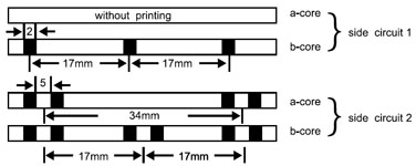 |
| The single core is identified by black ring markings: |
| Side Circuit 1 |
a-wire |
without marking |
| b-wire |
1 mark distance 17mm |
| Side Circuit 2 |
a-wire |
2 marks distance 34mm |
| b-wire |
2 marks distance 17mm |
| Subunits |
| Basic colours of the wire insulation of the 5 star quads of a basic unit: |
|
| |
Quad 1 |
Red |
|
| |
Quad 2 |
Green |
|
| |
Quad 3 |
Grey |
|
| |
Quad 4 |
Yellow |
|
| |
Quad 5 |
White |
|
| The tracer units are coded with a red helix, all other units by a white binder. |
|
| Dimensions and weight |
| |
VDE CODE: J-YY…x2x 0.6 Bd |
| |
| Cable Code |
Number of
Pairs |
Nominal Insulation
Thickness
mm |
Nominal Sheath
Thickness
mm |
Nominal Overall
Diameter
mm |
Nominal Weight
kg/km |
| 0.6mm Conductor, 1.0mm Insulted Wires |
| TP815J-YY-Bd-2P06 |
2 |
0.2 |
1.0 |
4.5 |
34 |
| TP815J-YY-Bd-4P06 |
4 |
0.2 |
1.0 |
6.5 |
59 |
| TP815J-YY-Bd-6P06 |
6 |
0.2 |
1.0 |
7.0 |
74 |
| TP815J-YY-Bd-10P06 |
10 |
0.2 |
1.0 |
8.5 |
111 |
| TP815J-YY-Bd-16P06 |
16 |
0.2 |
1.0 |
10.0 |
160 |
| TP815J-YY-Bd-20P06 |
20 |
0.2 |
1.0 |
11.0 |
200 |
| TP815J-YY-Bd-24P06 |
24 |
0.2 |
1.0 |
11.5 |
224 |
| TP815J-YY-Bd-30P06 |
30 |
0.2 |
1.2 |
13.0 |
284 |
| TP815J-YY-Bd-40P06 |
40 |
0.2 |
1.2 |
15.0 |
364 |
| TP815J-YY-Bd-50P06 |
50 |
0.2 |
1.2 |
16.5 |
451 |
| TP815J-YY-Bd-60P06 |
60 |
0.2 |
1.4 |
17.5 |
529 |
| TP815J-YY-Bd-80P06 |
80 |
0.2 |
1.4 |
20.3 |
700 |
| TP815J-YY-Bd-100P06 |
100 |
0.2 |
1.4 |
22.3 |
850 |
|
| |
|

