Power ground wire cable
![]() Application
Application
OPGW is a dual functioning cable performing the duties of a ground wire and also providing a patch for the transmission of voice, video or data signals . The fi bers are protected from environmental conditions (lightning, short circuit, loading) to ensure reliability and longevity. The cable is designed to be installed on transmission and distribution lines to carry voice, data and video communications, especially in lighting waveform monitoring system, an observation system for overhead test line, maintenance data information system, power line protection system, power line operation system, and unmanned substation monitoring.
![]() Description
Description
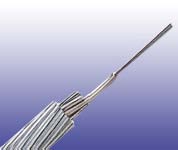
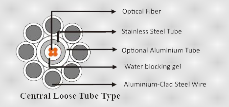
OPGW cable has two constructions: Central loose tube type.
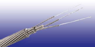
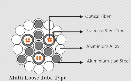
The fi bers is placed loosely in a sealed and water resistant stainless steel tube fi lled with water blocking gel. This tube provides protection to the fi bers during installation and operation under severe environmental conditions. Aluminium layer over the tube is optional. The stainless optical tube is located at the center of the cable protected by single or multiple layers of aluminium clad steel and aluminium alloy wires. The Aluminium-clad steel wires are shaped trapezoidally around the optical unit to provide compact construction. The metallic wires provide mechanical strength to withstand severe installation and operating conditions, while achieving conductivity to control temperature rise during short circuit conditions. This type can accommodate up to 48 fi bers in a cable. Despite such a high fi ber count in a single tube, each optical fi ber is clearly distinguishable utilizing a fi ber identifi cation system consisting of coloring and the number of ring marks on it. This compact design features high mechanical strength and fault current rating within a smaller diameter. The smaller diameter also results in excellent sag tension performance. Multi loose tube type--- The fi bers is placed loosely in a sealed and water resistant stainless steel tube fi lled with water blocking gel. Two or three stainless steel optical tubes are helically stranded in the inner layer of a multiple-layer cable.The multi loose tube type is designed mostly for very high fiber count requirement over 48 with the maximum fi ber count reaching 144. The multi loose tube type can meet the requirement of huge cross and large current capacity.
![]() Construction
Construction
 |
 |
 |
 |
![]() Physical Properties
Physical Properties
Cable section |
Nominal Outer Diameter |
Nominal Weight(kg/km)(lb/kft) |
Max working tension(kN) |
Modulus of clasticity(kN/mm2) |
Heat expansion coefficient(10-6/℃) |
DC Resistance |
Short-circuit current capacity |
35 |
8.1/0.318 |
250/167.79 |
45.2 |
162.0 |
13.0 |
2.433 |
8.9 |
50 |
9.6/0.378 |
343/230.20 |
63.0 |
162.0 |
13.0 |
1.743 |
16.5 |
70 |
11.4/0.448 |
487/326.85 |
89.3 |
162.0 |
13.0 |
1.237 |
3.04 |
90 |
12.5/0.492 |
368/246.98 |
58.2 |
94.1 |
17.3 |
0.473 |
72.7 |
105 |
13.5/0.531 |
428/287.25 |
67.9 |
94.1 |
17.3 |
0.403 |
98.8 |
130 |
15.0/0.590 |
527/353.69 |
83.8 |
94.1 |
17.3 |
0.329 |
149.9 |
* The effective sectional area of the single-layer design ranges from 50mm2 to 83mm2, suitable for rated voltages of 66kV, 115kV, 150kV, 250kV and 275kV. * The effective sectional area of the double-layer design ranges from 90mm2 to 200mm2, suitable for rated voltages of 150kV, 250kV, 275kV, 380kV and 500kV. * The effective sectional area of the three-layer design ranges from 200mm2 to 400mm2, suitable for rated voltages of 380kV, 420kV and 500kV in European markets.
![]() Mechanical Properities
Mechanical Properities
| Minimum Bending Radius: | Maximum Compressive Load: | 4000N for unarmoured | |
| Under installation: | 20×OD | 6000N for armoured | |
| During operation | 10×OD for unarmoured cables | Repeated Impact: | 4.4 N.m (J) |
| 20×OD for unarmoured cables | Twist (Torsion): | 180×10 times, 125×OD | |
| Temperature Range: | Cyclic Flexing: | 25 cycles for armoured cables. | |
| Operating Temperature Range: | -40℃(-40℉) to +70℃(+158℉) | 100 cycles for unarmoured cables. | |
| Storage Temperature Range: | -50℃(-58℉) to +70℃(+158℉) | Crush Resistance: | 220N/cm (125lb/in) |
![]() Fiber Compliance
Fiber Compliance
Temperature Cycling |
IEC60794-1-2-F2 |
![]() Standard Compliance
Standard Compliance
IEEE1138-1994
![]() Features
Features
• Colored coded fi bers and binders for quick and easy identifi cation during installation.
• Compact design results in excellent sag tension performance of the cable
• Aluminium-clad steel wires and Aluminium alloy wires provides mechanical strength to withstand the installation and operating conditions, while achieving conductivity required to control temperature rise, during the short circuit fault condition
• Optical unit placed inside the Aluminium tube provides exceptional mechanical and thermal protection for the fi ber against severe environments and external laternal force.
• Thick walled Aluminium tubes provide hermetic seal for optical units, providing excellent crush resistance and low resistivity.
• Unique design has maximum allowable tension to control fi ber strain
• Stranded wires used for optimizing the mechanical and electrical properties of the cables
• High load, long span capability.