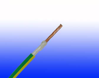
300/500V Mica+XLPE Insulated, LSZH Sheathed Power Cables (Single Core)
FFX300 05mRZ1-R (CU/MGT+XLPE/LSZH 300/500V Class 2)
APPLICATION
The cables are designed for areas where the integrity of the electrical circuit is critical in maintaining power supply. Applications can be found in emergency lightings, control and power circuits, power stations, fire alarm systems,underground tunnels, lifts, escalators, and high-rise buildings.
STANDARDS
- Basic design to IEC 60502-1
FIRE PERFORMANCE
| Circuit Integrity |
IEC 60331-21; BS 6387 CWZ; DIN VDE 0472-814(FE180);CEI 20-36/2-1; SS299-1; NBN C 30-004 (cat. F3);NF C32-070-2.3(CR1) |
| System circuit integrity |
DIN 4102-12, E30 depending on lay system |
| Flame Retardance (Single Vertical Wire Test) |
EN 60332-1-2; IEC 60332-1-2; BS EN 60332-1-2; VDE 0482-332-1; NBN C 30-004 (cat. F1); NF C32-070-2.1(C2); CEI 20-35/1-2; EN 50265-2-1*; DIN VDE 0482-265-2-1* |
| Reduced Fire Propagation (Vertically-mounted bundled wires & cable test) |
EN 60332-3-24 (cat. C); IEC 60332-3-24; BS EN 60332-3-24; VDE 0482-332-3; NBN C 30-004 (cat. F2); NF C32-070-2.2(C1);CEI 20-22/3-4; EN 50266-2-4*; DIN VDE 0482-266-2-4 |
| Halogen Free |
IEC 60754-1; EN 50267-2-1; DIN VDE 0482-267-2-1; CEI 20-37/2-1; BS 6425-1* |
| No Corrosive Gas Emission |
IEC 60754-2; EN 50267-2-2; DIN VDE 0482-267-2-2; CEI 20-37/2-2; BS 6425-2* |
| Minimum Smoke Emission |
IEC 61034-1&2; EN 61034 -1&2; DIN VDE 0482-1034-1&2; CEI 20-37/3-1&2; EN 50268-1&2*; BS 7622-1&2* |
| No Toxic gases |
NES 02-713; NF C 20-454 |
Note: Asterisk * denotes superseded standard.
VOLTAGE RATING
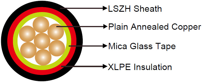
CABLE CONSTRUCTION
| Conductor |
Plain annealed copper wire, stranded according to IEC 60228 class 2 |
| Insulation |
Mica glass tape covered by extruded XLPE compound |
| Sheath |
Thermoplastic LSZH compound type LTS3 as per BS 7655-6.1 (Thermosetting LSZH compound type SW2-SW4 as per BS 7655-2.6 can be offered.). UV resistance, hydrocarbon resistance, oil resistance, anti rodent and anti termite properties can be offered as option |
COLOUR CODE
| Insulation colour upon request |
|
| Sheath Colour |
Black (other colours upon request) |
PHYSICAL AND THERMAL PROPERTIES
| Temperature range during operation (fixed state) |
-30°C – +90°C |
| Temperature range during installation (mobile state) |
-20°C – +50°C |
| Minimum bending radius |
8 x Overall Diameter |
ELECTRICAL PROPERTIES
| Dielectric test |
2000 V r.m.s. x 5’ (core/core) |
| Insulation resistance |
1000 MΩ x km (at 20°C) |
| Short circuit temperature |
250°C |
CONSTRUCTION PARAMETERS
| Conductor |
FFX300 05mRZ1-R |
| Nominal Cross Section Area |
No./Nominal Diameter of Strands |
Nominal Insulation Thickness |
Nominal Sheath Thickness |
Without Earth Conductor |
| Nominal Overall Diameter |
Approx. Weight |
| mm2 |
No./mm |
mm |
mm |
mm |
kg/km |
| 1.5 |
7/0.53 |
0.5 |
0.5 |
4.4 |
29 |
| 2.5 |
7/0.67 |
0.5 |
0.5 |
4.9 |
40 |
| 4 |
7/0.85 |
0.5 |
0.5 |
5.5 |
55 |
ELECTRICAL PROPERTIES
| Conductor Operating Temperature |
90°C |
| Ambient Temperature |
30°C |
Current-Carrying Capacities (Amp)
| Conductor crosssection area |
Reference Method 4(enclosed in conduit in thermally insulating wall etc) |
Reference Method 3 (enclosed in conduit on a wall or in trunking etc) |
Reference Method 1 (clipped direct) |
Reference Method 11 (on a perforated cable tray, horizontal or vertical) |
Reference Method 12 (free air) |
| Horizontal flat spaced |
Vertical flat spaced |
Trefoil |
| |
2 cables, single-phase a.c. or d.c. |
3 or 4 cables, -phase a.c. |
2 cables, single- |
3 or 4 cables, 3-phase a.c. |
2 cables, single-phase a.c. or d.c. flat and touching |
3 or 4 cables, 3-phase a.c. flat and touching or trefoil |
2 cables, single-phase a.c. or d.c. or flat and touching |
3 or 4 cables, 3-phase a.c. flat and touching or trefoil |
2 cables, single-phase a.c. or d.c. or 3 cables three phase |
2 cables, single-phase a.c. or d.c. or 3 cables three phase |
3 cables, trefoil 3-phase phase a.c. |
| phase a.c. a.c. or d.c |
| 1 |
2 |
3 |
4 |
5 |
6 |
7 |
8 |
9 |
10 |
11 |
12 |
| mm2 |
A |
A |
A |
A |
A |
A |
A |
A |
A |
A |
A |
| 1.5 |
18 |
17 |
22 |
19 |
25 |
23 |
- |
- |
- |
- |
- |
| 2.5 |
24 |
23 |
30 |
26 |
34 |
31 |
- |
- |
- |
- |
- |
| 4 |
33 |
30 |
40 |
35 |
46 |
41 |
- |
- |
- |
- |
- |
Voltage Drop (Per Amp Per Meter)
| Nominal Cross Section Area |
2 cables d.c. |
2 cables, single-phase a.c. |
3 or 4 cables, three-phase a.c. |
| Ref. Methods A and B (enclosed inconduit or trunking) |
Ref. Methods C, F&G(clipped direct, on trays or in free air) |
Ref. Methods 3 and 4 (enclosed in conduit etc,in or on a wall) |
Ref. Methods C, F&G (clipped direct, on trays or in free air) |
| Cables touching, Trefoil |
Cablestouching, Flat |
Cablesspaced*, Flat |
| 1 |
2 |
3 |
touching 4 |
spaced*5 |
6 |
7 |
8 |
9 |
| mm2 |
mV/A/m |
mV/A/m |
mV/A/m |
mV/A/m |
mV/A/m |
mV/A/m |
mV/A/m |
mV/A/m |
| 1.5 |
31 |
31 |
31 |
31 |
27 |
27 |
27 |
27 |
| 2.5 |
19 |
19 |
19 |
19 |
16 |
16 |
16 |
16 |
| 4 |
12 |
12 |
12 |
12 |
10 |
10 |
10 |
10 |
Note: *Spacings larger than one cable diameter will result in a large voltage drop.