Flame Retardant RG6 A/U CWB/SWB/SWA Armoured Coaxial Cables
APPLICATION
These 75Ω coaxial cables are suitable for installation on board of ships and other indoor marine environments.
STANDARDS
- Basic design adapted to MIL-C-17
FIRE PERFORMANCE
| Flame Retardance (Single Vertical Wire Test)** |
EN 60332-1-2; IEC 60332-1-2; BS EN 60332-1-2; VDE 0482-332-1; NBN C 30-004 (cat. F1); NF C32-070-2.1(C2); CEI 20-35/1-2; EN 50265-2-1*; DIN VDE 0482-265-2-1* |
| Reduced Fire Propagation (Vertically-mounted bundled wires & cable test)** |
EN 60332-3-22 (cat. A); IEC 60332-3-22; BS EN 60332-3-22; VDE 0482-332-3; NBN C 30-004 (cat. F2); NF C32-070-2.2(C1);CEI 20-22/3-4; EN 50266-2-4*; DIN VDE 0482-266-2-4 |
Note: Asterisk ** denotes that the standard compliance is optional, depending on the oxygen index of the PVC compound and the cable design.
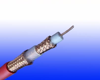
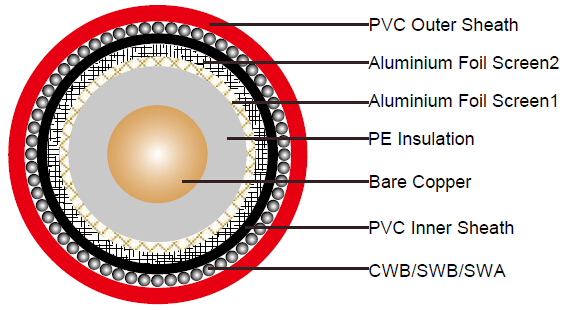
CABLE CONSTRUCTION
| Conductors |
18AWG bare copper wire, solid according to IEC 60228 class 1 |
| Insulation |
PE compound |
| Screen 1 |
Aluminium/polyester or aluminium tape |
| Screen 2 |
Tinned copper braid |
| Inner Sheath |
PVC compound |
| Armouring |
CWB:Copper Wire Braid
SWB:Steel Wire Braid
SWA:Steel Wire Armour |
| Outer Sheath |
Thermoplastic PVC compound. UV resistance, hydrocarbon resistance, oil resistance, anti rodent and anti termite properties can be offered as option. Compliance to fire performance standard (IEC 60332-1, IEC 60332-3, UL 1581, UL 1666 etc) depends on the oxygen index of the PVC compound and the overall cable design. LSPVC can also be provided upon request |
PHYSICAL AND THERMAL PROPERTIES
| Temperature Range |
-30°C - +75°C |
| Minimum Bending Radius |
15 X Overall Diameter |
ELECTRICAL PROPERTIES
| Impedance |
75±5Ω |
| Capacitance |
54 nF/km |
| Velocity ratio |
82% |
| Insulation resistance |
>5000 Mohm.Km |
| DC resistance |
|
| Inner conductor |
23.1 Ω/km |
| Outer conductor |
31 Ω/km |
ATTENUATION
| Frequency |
Attenuation |
Attenuation |
| MHz |
dB/100 m |
dB/100ft |
| 50 |
5.0 |
1.5 |
| 100 |
6.4 |
1.96 |
| 200 |
9.2 |
2.8 |
| 500 |
14.5 |
4.4 |
| 600 |
15.9 |
4.9 |
| 800 |
17.7 |
5.4 |
| 1000 |
21.9 |
6.7 |
| 1350 |
24.9 |
7.6 |
| 1750 |
29.0 |
8.8 |
| 2050 |
33.1 |
10.1 |
| 2400 |
36.4 |
11.1 |
RETURN LOSS
| Frequency |
Return Loss |
| MHz |
dB |
| 30-300 |
>28 |
| 300-600 |
>24 |
| 600-900 |
>22 |
CONSTRUCTION PARAMETERS
| Cable Code |
Nominal Inner Conductor Diameter |
Nominal Insulation Thickness |
Nominal Sheath Thickness |
Nominal Overall Diameter |
Nominal Weight |
| |
mm |
mm |
mm |
mm |
kg/km |
| FGD RG6/U CWB |
1.0 |
1.8 |
1.2 |
10.8 |
181 |
| FGD RG6/U SWB |
1.0 |
1.8 |
1.2 |
10.8 |
177 |
| FGD RG6/U SWA |
1.0 |
1.8 |
1.2 |
11.8 |
267 |