450/750V PVC Insulated, Non-sheathed Power Cables (Single Core)
FGD100 07V-R (CU/PVC 450/750V Class 2)
APPLICATION
The cables are mainly used in power stations, mass transit underground passenger systems, airports, petrochemical plants, hotels, hospitals, and high-rise buildings.
STANDARDS
- Basic design adapted to BS 6491X
FIRE PERFORMANCE
| Flame Retardance (Single Vertical Wire Test)** |
EN 60332-1-2; IEC 60332-1-2; BS EN 60332-1-2; VDE 0482-332-1; NBN C 30-004 (cat. F1); NF C32-070-2.1(C2); CEI 20-35/1-2; EN 50265-2-1*; DIN VDE 0482-265-2-1* |
| Reduced Fire Propagation (Vertically-mounted bundled wires & cable test)** |
EN 60332-3-22 (cat. A); IEC 60332-3-22; BS EN 60332-3-22; VDE 0482-332-3; NBN C 30-004 (cat. F2); NF C32-070-2.2(C1);CEI 20-22/3-4; EN 50266-2-4*; DIN VDE 0482-266-2-4 |
Note: Asterisk ** denotes that the standard compliance is optional, depending on the oxygen index of the PVC compound and the cable design.
VOLTAGE RATING
450/750 V
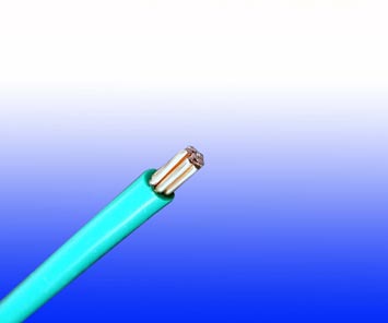
CABLE CONSTRUCTION
| Conductor |
Plain annealed copper wire, stranded according to IEC 60228 class 2 |
| Outer Sheath |
Thermoplastic PVC compound. UV resistance, hydrocarbon resistance, oil resistance, anti rodent and anti termite properties can be offered as option. Compliance to fire performance standard (IEC 60332-1, IEC 60332-3, UL 1581, UL 1666 etc) depends on the oxygen index of the PVC compound and the overall cable design. LSPVC can also be provided upon request |
COLOUR CODE
| Insulation Colour as per BS7671 |
|
| Sheath Colour |
Black (other colors upon request) |
PHYSICAL AND THERMAL PROPERTIES
| Maximum temperature range during operation (XLPE) |
90°C |
| Maximum short circuit temperature (5 Seconds) |
250°C |
| Minimum bending radius |
6 x Overall Diameter |
CONSTRUCTION PARAMETERS
| Conductor |
FGD100 07V-R |
| No. of Core X Cross Section |
No./Nominal Diameter of Strands |
Nominal Insulation Thickness |
Nominal Overall Diameter |
Approx. Weight |
| Noxmm2 |
No./mm |
mm |
mm |
kg/km |
| 1x1.5 |
7/0.53 |
0.7 |
3.1 |
23 |
| 1x2.5 |
7/0.67 |
0.8 |
3.7 |
35 |
| 1x4 |
7/0.85 |
0.8 |
4.3 |
52 |
| 1x6 |
7/1.04 |
0.8 |
4.8 |
73 |
| 1x10 |
7/1.35 |
1.0 |
6.2 |
120 |
| 1x16 |
7/1.70 |
1.0 |
7.2 |
180 |
| 1x25 |
7/2.24 |
1.2 |
9.0 |
285 |
| 1x35 |
19/1.53 |
1.2 |
10.2 |
375 |
| 1x50 |
19/1.78 |
1.4 |
12.0 |
510 |
| 1x70 |
19/2.14 |
1.4 |
14.0 |
720 |
| 1x95 |
19/2.52 |
1.6 |
16.0 |
995 |
| 1x120 |
37/2.03 |
1.6 |
18.0 |
1230 |
| 1x150 |
37/2.25 |
1.8 |
20.0 |
1520 |
| 1x185 |
37/2.52 |
2.0 |
22.0 |
1900 |
| 1x240 |
61/2.25 |
2.2 |
25.0 |
2480 |
| 1x300 |
61/2.52 |
2.4 |
28.0 |
3100 |
| 1x400 |
61.2.85 |
2.6 |
31.5 |
3950 |
| 1x500 |
61/3.20 |
2.8 |
35.0 |
4950 |
| 1x630 |
127/2.52 |
2.8 |
39.0 |
6360 |
ELECTRICAL PROPERTIES
| Conductor Operating Temperature |
70°C |
| Ambient Temperature |
30°C |
Current-Carrying Capacities (Amp)
| Conductor
cross-sectional
area |
Reference Method A (enclosed inconduit in thermally insulating walletc) |
Reference Method B (enclosed inconduit on a wall or in trunking etc) |
Reference Method C (clipped direct) |
Reference Method F (in free air or on a perforated cable tray, horizontal or vertical etc) Touching |
Reference MethodG (in free air) Spaced by one cable diameter |
| 2 cables,
single-phase
a.c. or d.c. |
3 or 4 cables,three-phase a.c. |
2 cables,
single-phase
a.c. or d.c |
3 or 4 cables,
three-phase a.c. |
2 cables,
single-phase
a.c. or d.c.
flat andtouching |
3 or 4 cables,
three-phase a.c.
flat and touching
or trefoil |
2 cables,
single-phase
a.c. or d.c. flat |
3 cables,
three-phase
a.c. flat |
3 cables,
three-phase
a.c. trefoil |
2 cables,
single-phase
a.c. or d.c. or 3 cables
three-phase a.c. flat |
| Horizontal |
Vertical |
| 1 |
2 |
3 |
4 |
5 |
6 |
7 |
8 |
9 |
10 |
11 |
12 |
| mm2 |
A |
A |
A |
A |
A |
A |
A |
A |
A |
A |
A |
| 1.5 |
14.5 |
13.5 |
17.5 |
15.5 |
20 |
18 |
- |
- |
- |
- |
- |
| 2.5 |
20 |
18 |
24 |
21 |
27 |
25 |
- |
- |
- |
- |
- |
| 4 |
26 |
24 |
32 |
28 |
37 |
33 |
- |
- |
- |
- |
- |
| 6 |
34 |
31 |
41 |
36 |
47 |
43 |
- |
- |
- |
- |
- |
| 10 |
46 |
42 |
57 |
50 |
65 |
59 |
- |
- |
- |
- |
- |
| 16 |
61 |
56 |
76 |
68 |
87 |
79 |
- |
- |
- |
- |
- |
| 25 |
80 |
73 |
101 |
89 |
114 |
104 |
131 |
114 |
110 |
146 |
130 |
| 35 |
99 |
89 |
125 |
110 |
141 |
129 |
162 |
143 |
137 |
181 |
162 |
| 50 |
119 |
108 |
151 |
134 |
182 |
167 |
196 |
174 |
167 |
219 |
197 |
| 70 |
151 |
136 |
192 |
171 |
234 |
214 |
251 |
225 |
216 |
281 |
254 |
| 95 |
182 |
164 |
232 |
207 |
284 |
261 |
304 |
275 |
264 |
341 |
311 |
| 120 |
210 |
188 |
269 |
239 |
330 |
303 |
352 |
321 |
308 |
396 |
362 |
| 150 |
240 |
216 |
300 |
262 |
381 |
349 |
406 |
372 |
356 |
456 |
419 |
| 185 |
273 |
245 |
341 |
296 |
436 |
400 |
463 |
427 |
409 |
521 |
480 |
| 240 |
321 |
286 |
400 |
346 |
515 |
472 |
546 |
507 |
485 |
615 |
569 |
| 300 |
367 |
328 |
458 |
394 |
594 |
545 |
629 |
587 |
561 |
709 |
659 |
| 400 |
- |
- |
546 |
467 |
694 |
634 |
754 |
689 |
656 |
852 |
795 |
| 500 |
- |
- |
626 |
533 |
792 |
723 |
868 |
789 |
749 |
982 |
920 |
| 630 |
- |
- |
720 |
611 |
904 |
826 |
1005 |
905 |
855 |
1138 |
1070 |
Voltage Drop (Per Amp Per Meter)
| Nominal
Cross Section Area |
2 cables
d.c. |
2 cables, single-phase a.c. |
3 or 4 cables, three-phase a.c. |
| Ref. Methods A and B (enclosed in conduit ortrunking) |
Ref. Methods C, F&G(clipped direct, on trays or in free air) |
Ref. Methods 3 and 4 (enclosed in conduit etc, in or on a wall) |
Ref. Methods C, F&G(clipped direct, on trays or in free air) |
| Cables touching,Trefoil |
Cables touching, Flat |
Cables spaced*, Flat |
| 1 |
2 |
3 |
Cables touching 4 |
Cables spaced*5 |
6 |
7 |
8 |
9 |
| mm2 |
mV/A/m |
mV/A/m |
mV/A/m |
mV/A/m |
mV/A/m |
mV/A/m |
mV/A/m |
mV/A/m |
| 1.5 |
29 |
29 |
29 |
29 |
25 |
25 |
25 |
25 |
| 2.5 |
18 |
18 |
18 |
18 |
15 |
15 |
15 |
15 |
| 4 |
11 |
11 |
11 |
11 |
9.5 |
9.5 |
9,5 |
9.5 |
| 6 |
7.3 |
7.3 |
7.3 |
7.3 |
6.4 |
6.4 |
6.4 |
6.4 |
| 10 |
4.4 |
4.4 |
4.4 |
4.4 |
3.8 |
3.8 |
3.8 |
3.8 |
| 16 |
2.8 |
2.8 |
2.8 |
2.8 |
2.4 |
2.4 |
2.4 |
2.4 |
| |
|
r |
x |
z |
r |
x |
z |
r |
x |
z |
r |
x |
z |
r |
x |
z |
r |
x |
z |
r |
x |
z |
| 25 |
1.75 |
1.80 |
0.33 |
1.80 |
1.75 |
0.20 |
1.75 |
1.75 |
0.29 |
1.80 |
1.50 |
0.29 |
1.55 |
1.50 |
0.175 |
1.50 |
1.50 |
0.25 |
1.55 |
1.50 |
0.32 |
1.55 |
| 35 |
1.25 |
1.30 |
0.31 |
1.30 |
1.25 |
0.195 |
1.25 |
1.25 |
0.28 |
1.30 |
1.10 |
0.27 |
1.10 |
1.10 |
0.170 |
1.10 |
1.10 |
0.24 |
1.10 |
1.10 |
0.32 |
1.15 |
| 50 |
0.93 |
0.95 |
0.30 |
1.00 |
0.93 |
0.190 |
0.95 |
0.93 |
0.28 |
0.97 |
0.81 |
0.26 |
0.85 |
0.80 |
0.165 |
0.82 |
0.80 |
0.24 |
0.84 |
0.80 |
0.32 |
0.86 |
| 70 |
0.63 |
0.65 |
0.29 |
0.72 |
0.63 |
0.185 |
0.66 |
0.63 |
0.27 |
0.69 |
0.56 |
0.25 |
0.61 |
0.55 |
0.160 |
0.57 |
0.55 |
0.24 |
0.60 |
0.55 |
0.31 |
0.63 |
| 95 |
0.46 |
0.49 |
0.28 |
0.56 |
0.47 |
0.180 |
0.50 |
0.47 |
0.27 |
0.54 |
0.42 |
0.24 |
0.48 |
0.41 |
0.155 |
0.43 |
0.41 |
0.23 |
0.47 |
0.40 |
0.31 |
0.51 |
| 120 |
0.36 |
0.39 |
0.27 |
0.47 |
0.37 |
0.175 |
0.41 |
0.37 |
0.26 |
0.45 |
0.33 |
0.23 |
0.41 |
0.32 |
0.150 |
0.36 |
0.32 |
0.23 |
0.40 |
0.32 |
0.30 |
0.44 |
| 150 |
0.29 |
0.31 |
0.27 |
0.41 |
0.30 |
0.175 |
0.34 |
0.29 |
0.26 |
0.39 |
0.27 |
0.23 |
0.36 |
0.26 |
0.150 |
0.30 |
0.26 |
0.23 |
0.34 |
0.26 |
0.30 |
0.40 |
| 185 |
0.23 |
0.25 |
0.27 |
0.37 |
0.24 |
0.170 |
0.29 |
0.24 |
0.26 |
0.35 |
0.11 |
0.23 |
0.32 |
0.21 |
0.145 |
0.26 |
0.21 |
0.22 |
0.31 |
0.21 |
0.30 |
0.36 |
| 240 |
0.180 |
0.195 |
0.26 |
0.33 |
0.185 |
0.165 |
0.25 |
0.185 |
0.25 |
0.31 |
0.17 |
0.23 |
0.29 |
0.160 |
0.145 |
0.22 |
0.160 |
0.22 |
0.27 |
0.160 |
0.29 |
0.34 |
| 300 |
0.145 |
0.160 |
0.26 |
0.31 |
0.150 |
0.165 |
0.22 |
0.150 |
0.25 |
0.29 |
0.14 |
0.23 |
0.27 |
0.130 |
0.140 |
0.190 |
0.130 |
0.22 |
0.25 |
0.130 |
0.29 |
0.32 |
| 400 |
0.105 |
0.130 |
0.26 |
0.29 |
0.120 |
0.160 |
0.20 |
0.115 |
0.25 |
0.27 |
0.12 |
0.22 |
0.25 |
0.105 |
0.140 |
0.175 |
0.105 |
0.21 |
0.24 |
0.100 |
0.29 |
0.31 |
| 500 |
0.086 |
0.110 |
0.26 |
0.28 |
0.098 |
0.155 |
0.185 |
0.093 |
0.24 |
0.26 |
0.10 |
0.22 |
0.25 |
0.086 |
0.135 |
0.160 |
0.086 |
0.21 |
0.23 |
0.081 |
0.29 |
0.30 |
| 630 |
0.068 |
0.094 |
0.25 |
0.27 |
0.081 |
0.155 |
0.175 |
0.076 |
0.24 |
0.25 |
0.08 |
0.21 |
0.24 |
0.072 |
0.135 |
0.150 |
0.072 |
0.21 |
0.22 |
0.066 |
0.28 |
0.29 |
Note: *Spacings larger than one cable diameter will result in a large voltage drop.
r = conductor resistance at operating temperature
x = reactance
z = impedance