Photovoltaic Cable
Applications
PHOTOFLEX Photovoltaic Cable are designed for connecting photovoltaic system components inside and outside of buildings and equipment with high mechanical requirements and extreme weather conditions.This product type is TUV approved.
Standards
DIN EN 50618 (H1Z2Z2-K)
Certificate
TUV MARK - EN 50618 
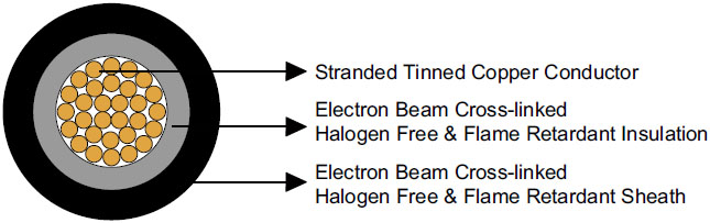
Construction
| Conductor |
Stranded tinned copper conductor per DIN VDE 0295 and IEC 60228 Class 5. |
| Insulation |
Electron beam cross-linked, halogen free and flame retardant compound. |
| Sheath |
Electron beam cross-linked, LSZH and flame retardant compound, Black. |
Electrical Properties
| Rated Voltage U0/U |
1/1 kV AC; 1.5/1.5 kV DC |
| Maximum Permitted DC Voltage |
1.8 kV DC (conductor/conductor, non earthed system, circuit not under load) |
| Insulation Resistance |
1000 MΩ-km |
| Spark Test |
6000 Vac (8400 Vdc) |
| Voltage Withstand |
6500 Vac for 5 minElectron |
Thermal Properties
| Maximum Voltage |
1.2KV (AC), 1.8KV (DC) |
| Ambient Temperature |
-40℃ ~ +90℃ |
| Maximum Temperature At Conductor |
120℃ (20000h) according to IEC/EN 60216-1 |
| Short Circuit Temperature |
200℃/5 sec |
| Thermal Endurance Test |
According to EN 60216-2 (temperature index +120° C) |
| Damp-Heat Resistance |
According to EN 50618, Table 2with 85% humidity(test acc. to EN 60068-2-78) |
Mechanical Properties
| Minimum Bending Radius |
4×OD (fixed), 5×OD (flexing) |
| Dynamic Penetration |
According to Acc. to EN 50618, Annex D,Meets requirements of EN 50618. |
| Tensile Strength And Elongation Of Insulation And Jacket |
250℃ |
| Anticipated Period Of Use |
25 years |
| Ovality |
≤15% |
Chemical Properties
| Ozone Resistance |
According to EN 60811-403(25℃,24h,(250 to 300) × 10-4%) ;Method B: EN 50396(40℃,72h,55%RH, (200 × 10-6%) |
| Weathering- UV Resistance (Resistance on sheath) |
Tensile strength and elongation at break after 720h (360 Cycles) of exposure to UV lights (acc. to EN 50289-4-17, Method A According to HD 605/A1) |
| Ammoniac resistant |
| Very good resistance to oils and chemicals |
| High wear and robust, abrasion resistant |
EC directives
The cables are conform to the EC directives CE 2006/95/EC (Low voltage directive) and RoHS 2002/95/EC (Restriction of Hazardous Substances).
Fire Performance
| Flame retardant according to EN 50265-2-1, IEC 60332-1, VDE 0482-332-1-2, DIN EN 60332-1-2 |
| Low smoke emission according to EN 61034-2 (Light Transmittance ≥60%) |
| Halogen free according to EN 50525-1, Annex B |
| Low corrosivity of gases according to EN 50267-2-2, IEC 60754-2 |
Dimensions and Weight
| No. of Cores × Nominal Cross Section |
No. of Stranding |
Nominal Conductor Diameter |
Nominal Insulation Thickness |
Nominal Sheath Thickness |
Nominal Overall Diamater |
Nominal Weight |
| No. ×mm^2 |
|
mm |
mm |
mm |
mm |
kg/km |
| 1×1.5 |
30/0.25 |
1.58 |
0.70 |
0.80 |
5.4 |
40 |
| 1×2.5 |
50/0.25 |
2.04 |
0.70 |
0.80 |
5.9 |
50 |
| 1×4.0 |
56/0.30 |
2.59 |
0.70 |
0.80 |
6.6 |
70 |
| 1×6.0 |
84/0.30 |
3.17 |
0.70 |
0.80 |
7.4 |
80 |
| 1×10 |
78/0.40 |
4.07 |
0.70 |
0.80 |
8.8 |
130 |
| 1×16 |
128/0.40 |
5.22 |
0.70 |
0.90 |
10.1 |
200 |
| 1×25 |
199/0.40 |
6.51 |
0.90 |
1.00 |
12.5 |
290 |
| 1×35 |
279/0.40 |
7.71 |
0.90 |
1.10 |
14.0 |
400 |
| 1×50 |
396/0.40 |
9.00 |
1.00 |
1.20 |
16.3 |
550 |
| 1×70 |
360/0.50 |
10.8 |
1.10 |
1.20 |
18.7 |
750 |
| 1×95 |
475/0.50 |
12.6 |
1.10 |
1.30 |
20.8 |
970 |
| 1×120 |
608/0.50 |
14.2 |
1.20 |
1.30 |
22.8 |
1220 |
| 1×150 |
756/0.50 |
15.8 |
1.40 |
1.40 |
25.5 |
1510 |
| 1×185 |
925/0.50 |
17.4 |
1.60 |
1.60 |
28.5 |
1850 |
| 1×240 |
1221/0.50 |
20.4 |
1.70 |
1.70 |
32.1 |
2400 |
Current Carrying Capacity
| Cross Section |
AWG |
Maximum Conductor Resistance at 20℃ |
Maximum insulation Resistance at 20℃ |
Maximum insulation Resistance at 90℃ |
Current Carrying Capacity |
| Single cable free in air |
Single cable on surfaces |
2 loaded cables adjacent on surfaces |
| mm^2 |
- |
Ω |
MΩ.km |
MΩ.km |
A |
A |
A |
| 1.5 |
16 |
13.7 |
859 |
0.859 |
30 |
29 |
24 |
| 2.5 |
14 |
8.21 |
691 |
0.691 |
41 |
39 |
33 |
| 4 |
12 |
5.09 |
579 |
0.579 |
55 |
52 |
44 |
| 6 |
10 |
3.39 |
499 |
0.499 |
70 |
67 |
57 |
| 10 |
8 |
1.95 |
424 |
0.424 |
98 |
93 |
79 |
| 16 |
6 |
1.24 |
342 |
0.342 |
132 |
125 |
107 |
| 25 |
4 |
0.795 |
339 |
0.339 |
176 |
167 |
142 |
| 35 |
2 |
0.565 |
287 |
0.287 |
218 |
207 |
176 |
| 50 |
1/0 |
0.393 |
268 |
0.268 |
276 |
262 |
221 |
| 70 |
2/0 |
0.277 |
247 |
0.247 |
347 |
330 |
278 |
| 95 |
3/0 |
0.210 |
220 |
0.220 |
416 |
395 |
333 |
| 120 |
4/0 |
0.164 |
211 |
0.211 |
488 |
464 |
390 |
| 150 |
300 kcmil |
0.132 |
206 |
0.206 |
566 |
538 |
453 |
| 185 |
350 kcmil |
0.108 |
200 |
0.200 |
644 |
612 |
515 |
| 240 |
450 kcmil |
0.082 |
198 |
0.198 |
775 |
736 |
620 |
Conversion Factor for Deviating Temperatures
| Ambient Temperature ℃ |
Conversion Factor |
| Up to 60 |
1.00 |
| 70 |
0.91 |
| 80 |
0.82 |
| 90 |
0.71 |
| 100 |
0.58 |
| 110 |
0.41 |
Reduction factor for accumulation according to IEC 60364-5-52, Table B.52-17